Autonerdz Home Autonerdz FAQ User’s Comments Autonerdz Events Autonerdz Store Contact Autonerdz

Autonerdz forums

 
  Welcome, Guest. Please Login or Register
Autonerdz - Since 2000, North America's Authority on PicoScope
 
  HomeHelpSearch Member Map Event CalendarRegisterLogin  
 
Pages: 1 2 3 
Ford CMP vs. CKP synchronization (Read 158,047 times)
Doug S.
Super Nerd
Picogroup
*****
Offline


I love YaBB 1G - SP1!

Posts: 620

Everett, Washington, USA
Everett
Washington
USA

Gender: male
Ford CMP vs. CKP synchronization
Feb 21st, 2004 at 7:19am
 
Tom,
In your classes and on the website, you talk about Ford Camshaft Position Sensor synchronization.  There are pictures of how it appears with the Fluke 97 (I believe) on the website.  Do you have any pictures as it appears with the Picoscope and can you discuss this a little for people that have never synchronized one?  Thanks, Ziggee.
Back to top
 
 
IP Logged
 
Tom Roberts
Autonerdz Administrator
Picogroup
*****
Offline


Autonerdz Founder

Posts: 8,595

Olympia, Washington, USA
Olympia
Washington
USA

Gender: male
Re: Ford CMP vs. CKP synchronization
Reply #1 - Feb 21st, 2004 at 9:47am
 
Sure, Ziggee  Wink

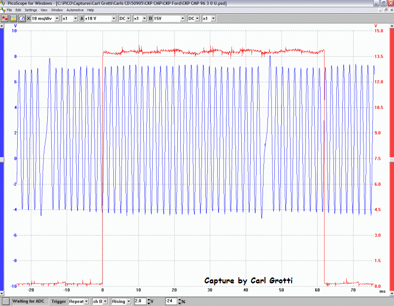
Here is how the CKP and CMP look:

...

The crank signal is a 36 minus one tooth ring and the missing tooth is at 60 degrees BTDC, for a 6 cyl.  The sensor is a floating ground type VRS, so be sure to stab the correct wire so the signal is 'right side up'.  The signal should rise in the missing tooth region when you have it right.  The center of each tooth is 10 degrees.  The signal crosses zero going negative as the center of a tooth aligns.  Don't be concerned that the signal 'floats' a bit above ground.  This is normal because it's a floater and we have the scope referenced to vehicle ground.

The Cam signal is a hall effect 180 degree signal.  It's high for one crank rotation and low for the next.

We can set these up with the CMP rising or falling edge.
...

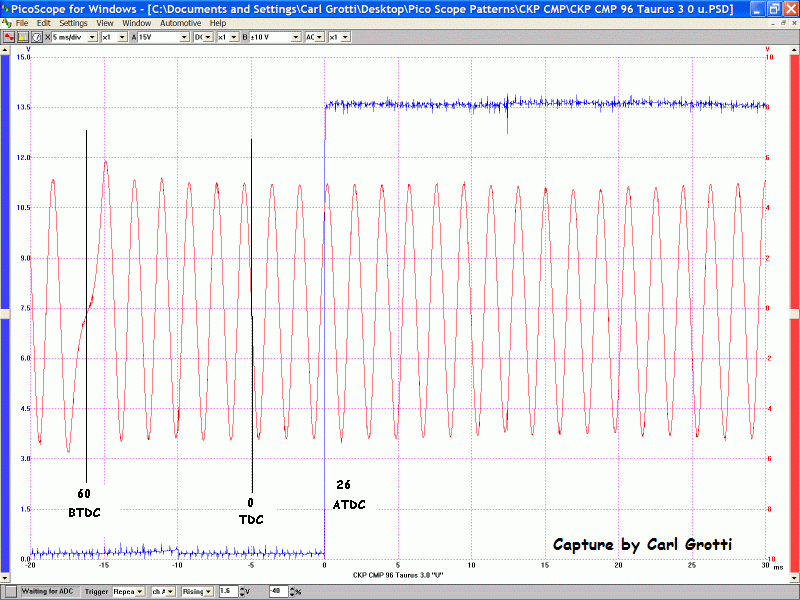
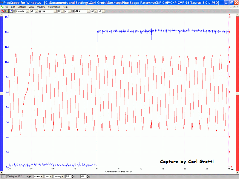
Here, we use the rising edge.

...

Here we have added the degree markings.  The rising edge of the cam signal should be at 26 ATDC #1 so 180 degrees of cam rotation later it will fall at 26 ATDC #5.

The cam sensor can be installed 180 degrees out and the signal will look perfect and the PCM will not know the difference but inject fuel at the wrong cylinder at the wrong time.

You can use compression #1 or #5 to set these up. Just be sure the CMP falls ATDC #5 and rises ATDC #1. I rough them in by hand then do the fine adjustment with the scope, engine running. In some applications, like the Windstar, rather than shedding blood to remove the #1 plug, I just use #5. Keeping in mind that the CMP vane should be leaving the sensor instead of entering it as it would be for #1 compression.

This procedure works for any EDIS 6 cyl with a hall effect cam sensor.
Back to top
« Last Edit: Jan 12th, 2023 at 8:54am by Brian Haley »  

Tom Roberts
Forums Administrator
 
IP Logged
 
Romain.
Senior Member
Picogroup
***
Offline


Deceased

Posts: 212

Gender: male
Re: Ford CMP vs. CKP synchronization
Reply #2 - Feb 21st, 2004 at 2:38pm
 
Hi Tom,

The above waves show the HALL switch type of CAM sensor in relation to the VRS CRANK sensor.
Any chance that you can show a relationship with the VRS CRANK sensor and the VRS CAM sensor as used on some Fords, if you have one in your archives that is ?
Back to top
 
 
IP Logged
 
Tom Roberts
Autonerdz Administrator
Picogroup
*****
Offline


Autonerdz Founder

Posts: 8,595

Olympia, Washington, USA
Olympia
Washington
USA

Gender: male
Re: Ford CMP vs. CKP synchronization
Reply #3 - Feb 21st, 2004 at 4:43pm
 
OK Romain,

The negative going edge of the VRS type CMP is located at 22 degrees ATDC #1. 

...

The above is typical six cylinder sync.  It's more difficult to be exact here, but we have some tolerance.

...

The above is an example from a 1.9 four cylinder.  This one is not adjustable.  Also, on the four cyl, the missing tooth on the CKP is at 90 degrees BTDC.
Back to top
 

Tom Roberts
Forums Administrator
 
IP Logged
 
Romain.
Senior Member
Picogroup
***
Offline


Deceased

Posts: 212

Gender: male
Re: Ford CMP vs. CKP synchronization
Reply #4 - Feb 21st, 2004 at 8:00pm
 
Thanks Tom, I have not encountered one to use the PICO scope on, I did some reading and discovered that the PCM reads the signal where the wave is going negative to a point just below the 0 line.
just wondered why not at the 0 line.
Back to top
 
 
IP Logged
 
Tom Roberts
Autonerdz Administrator
Picogroup
*****
Offline


Autonerdz Founder

Posts: 8,595

Olympia, Washington, USA
Olympia
Washington
USA

Gender: male
Re: Ford CMP vs. CKP synchronization
Reply #5 - Feb 21st, 2004 at 8:31pm
 
Hi Romain,

Where the PCM trigggers has to do with it's own internal circuitry.  I don't know the whys.

Carl contributed a couple more I thought were interesting.

...

The above capture is a V8.  The missing tooth area is at 50 degrees BTDC for the V8.  We are still using the 36 minus one CKP.

...

This one is the V10.  The CKP is a 40 minus one tooth CKP and the missing tooth is at 36 degrees BTDC.  So we'll count 9 degrees for a tooth and that puts this VRS CMP at about 26 ATDC.  I don't think these are adjustable either.

You'll be fine shooting for 26 degrees ATDC for either the Hall effect style or the VRS style CMP when adjustment is possible.
Back to top
 

Tom Roberts
Forums Administrator
 
IP Logged
 
andyjl
Freshman Member
*
Offline


I love YaBB 1G - SP1!

Posts: 9

Re: Ford CMP vs. CKP synchronization
Reply #6 - Feb 7th, 2006 at 3:31pm
 
Hi everyone,
I was wondering if you can just use another scope channel on secondary ignition number one or number five instead of pulling a plug to confirm compression on one or five being that the computer maintains spark firing order timed off the missing tooth on crank  even without a cam signal present at all       God forbid I wouldnt want to do things the hard way!!!! Wink     I realize the timing would float around some so it cant be used as a reference point for actually setting the sensor but it would be a quicker way of getting the up or down  direction right on the cam sensor would it not???????
Back to top
 
 
IP Logged
 
Tom Roberts
Autonerdz Administrator
Picogroup
*****
Offline


Autonerdz Founder

Posts: 8,595

Olympia, Washington, USA
Olympia
Washington
USA

Gender: male
Re: Ford CMP vs. CKP synchronization
Reply #7 - Feb 7th, 2006 at 4:15pm
 
Absolutely!  This procedure was written for two channel scope use.  The advantage of a third channel allows you to see where the compression firing is so you know at a glance where the engine is in its cycle:

...
Back to top
 

Tom Roberts
Forums Administrator
 
IP Logged
 
andyjl
Freshman Member
*
Offline


I love YaBB 1G - SP1!

Posts: 9

Re: Ford CMP vs. CKP synchronization
Reply #8 - Feb 8th, 2006 at 7:59am
 
hail the King.
thanks never done it but was wondering and there you have it!!!!!also that uses multistrike cool!
Back to top
 
 
IP Logged
 
Tom Roberts
Autonerdz Administrator
Picogroup
*****
Offline


Autonerdz Founder

Posts: 8,595

Olympia, Washington, USA
Olympia
Washington
USA

Gender: male
Re: Ford CMP vs. CKP synchronization
Reply #9 - Feb 8th, 2006 at 12:19pm
 
That's from a 2001 Windstar 3.8 IEDIS.  It multistrikes at idle and low RPM.

Keep in mind though that you can't do this with many scopes.  The sample rate has to be high enough to reliably detect the secondary KV at longer time bases, when multiple channels are being used.  The KV event may be only 10 millionths of a second (microseconds) wide.  If the samples are not close enough together you can't rely on identifying the compression KV event.


At this setting the PicoScope 3423 is sampling every 1.6 microseconds so it's not a problem.  We could put even more time on the screen, if we wanted.

You should be able to accomplish something similar with your Modis using a 1ms screen time.


Back to top
 

Tom Roberts
Forums Administrator
 
IP Logged
 
Tom Roberts
Autonerdz Administrator
Picogroup
*****
Offline


Autonerdz Founder

Posts: 8,595

Olympia, Washington, USA
Olympia
Washington
USA

Gender: male
Re: Ford CMP vs. CKP synchronization
Reply #10 - Mar 8th, 2006 at 9:34am
 
More on hook up logistics when working with floating ground VR sensors:

Incorrect scope hook up can create problems with the
vehicle or even cause a no start condition. Ford EDIS cam
sync is a great example. The CKP is a floater and the CMP
is either a hall effect or a non-floating VRS. The common
mistake is to hook a channel input and ground across the
CKP. That works fine if that is the only channel you intend
to use and you will get an accurate representation of the
CKP amplitude. But that doesn't help you sync. You have to
use another channel on the CMP. But your scope is now
grounded to something generating voltage ;-p If you use
another channel, weird things are going to happen. This is
because, on most scopes, the channels share that common
ground. The CKP voltage will cross feed through the scope
to someplace it shouldn't be.

The correct method is to reference all channels to vehicle
ground and back probe only one of the CKP wires with your
scope channel input. You must choose the correct wire so
your waveform is right side up to get your degree count
right. The other wire provides a pattern that is inverted
and will throw off your crank degree count. Hooking up this
way will allow you to use multiple channels with no
problems. However, it will make the CKP waveform reduced in
true peak to peak amplitude and it will appear to 'float'
above the ground line when the scope is DC coupled. Neither
of these issues is a problem if you are looking to sync the
CKP/CMP.

If you are looking to measure the CKP peak to peak volts,
however, this will not do. You will have to dedicate one
channel to this task and hook channel signal and ground
across the sensor to get this information. No other
channels should be deployed.

So, how you hook up depends on the information you want.

Non floating sensors like the EDIS VRS CMP have the signal
present on only one of the wires and display accurate peak
to peak results with the scope referenced to vehicle
ground. So, these do not require a separate hook up to get
this information.
Back to top
 

Tom Roberts
Forums Administrator
 
IP Logged
 
Danny Berry, Sr.
Super Nerd
Picogroup
*****
Offline


Elevation 840ft

Posts: 710

McDonough, Ga., Georgia, USA
McDonough, Ga.
Georgia
USA

Gender: male
Re: Ford CMP vs. CKP synchronization
Reply #11 - Sep 24th, 2007 at 8:46pm
 
Hay Tom,

This is cool for a ford. How about the same thing for a  1999 G.M 4.6 liter Northstar Cadillac Engine for something different. Also do you have pico scope wave forms for the 4x and 24x reference signals (4 ref high and 24x crnk that are sent to the pcm for ignition control. Camshaft reference (ref. lo/cam high) sent to the pcm for fuel injection control, or anything other functions associated with the ICM.

Thanks,

Danny B.
Smiley

Getting sleepy going to bed Wink Hope to read abput it later Smiley


Tom Roberts wrote on Feb 21st, 2004 at 9:47am:
Sure, Ziggee  Wink

Here is how the CKP and CMP look:

[img]

The crank signal is a 36 minus one tooth ring and the missing tooth is at 60 degrees BTDC, for a 6 cyl.  The sensor is a floating ground type VRS, so be sure to stab the correct wire so the signal is 'right side up'.  The signal should rise in the missing tooth region when you have it right.  The center of each tooth is 10 degrees.  The signal crosses zero going negative as the center of a tooth aligns.  Don't be concerned that the signal 'floats' a bit above ground.  This is normal because it's a floater and we have the scope referenced to vehicle ground.

The Cam signal is a hall effect 180 degree dignal.  It's high for one crank rotation and low for the next.

We can set these up with the CMP rising or falling edge.

[img]

Here, we use the rising edge.

[img]

Here we have added the degree markings.  The rising edge of the cam signal should be at 26 ATDC #1 so 180 degrees of cam rotation later it will fall at 26 ATDC #5.

The cam sensor can be installed 180 degrees out and the signal will look perfect and the PCM will not know the difference but inject fuel at the wrong cylinder at the wrong time.

You can use compression #1 or #5 to set these up. Just be sure the CMP falls ATDC #5 and rises ATDC #1. I rough them in by hand then do the fine adjustment with the scope, engine running. In some applications, like the Windstar, rather than shedding blood to remove the #1 plug, I just use #5. Keeping in mind that the CMP vane should be leaving the sensor instead of entering it as it would be for #1 compression.

This procedure works for any EDIS 6 cyl with a hall effect cam sensor.

Back to top
 
 
IP Logged
 
Tom Roberts
Autonerdz Administrator
Picogroup
*****
Offline


Autonerdz Founder

Posts: 8,595

Olympia, Washington, USA
Olympia
Washington
USA

Gender: male
Re: Ford CMP vs. CKP synchronization
Reply #12 - Sep 24th, 2007 at 10:47pm
 
Hi Danny,

I don't have much Northstar stuff but I'm sure someone does.   Wink
Back to top
 

Tom Roberts
Forums Administrator
 
IP Logged
 
twelch
Freshman Member
Picogroup
*
Offline


I love YaBB 1G - SP1!

Posts: 36

Re: Ford CMP vs. CKP synchronization
Reply #13 - Sep 25th, 2007 at 6:50am
 
I just did a quick search of the iATN waveform library. There are captures of 99 4.6 Cadillac cam/crank. The ones I saw were Modis but I didn't look for very long.
Back to top
 
 
IP Logged
 
Rick Hill
LSD Guide
Picogroup
*****
Offline


Deceased

Posts: 660

Gender: male
Re: Ford CMP vs. CKP synchronization
Reply #14 - Sep 25th, 2007 at 8:09am
 
Tom here is an ford 5.4  3 valve with variable cam timing.  I haven't figured out what fords logic was in where they placed this one. Those with vct  will have the number of signals equal to the number of cylinders on the bank plus one in one full revolution of the cam or 2 revolutions of the crank.  The 2.0 four cylinder z tech will have a signal like this v8 .  Four cylinders plus one equal to 5 signals. On the z tech the first wave will fall at about 22 degrees atc for #1 and #4. The set with 3 waves will be at tdc compression for #1 and the set with 2 waves will be at tdc compression for #4. That seems to go right along with the other ford vrs cam sensors being at 22 degrees atc but this v8  seems to not go along with that logic. The second wave in the set of three is close.  This cam is installed quite a bit advanced and the second wave in the set of three might come out right when the cam is retarded to where the bottom timing is straight up. It's a sohc motor and it's advanced I assume because they are using the cam as an egr in the retarded position and to move the torque curve in the advanced position so it's kind of dual purpose.
Back to top
 

Rick Hill
 
IP Logged
 
Pages: 1 2 3