The Autonerdz Community Forums
https://www.autonerdz.com/cgi/yabb2/YaBB.pl
General Public Area >> PicoScope >> Maths channel - crank sensor to frequency
https://www.autonerdz.com/cgi/yabb2/YaBB.pl?num=1392359817

Message started by andyz on Feb 13th, 2014 at 10:36pm

Title: Maths channel - crank sensor to frequency
Post by andyz on Feb 13th, 2014 at 10:36pm
Apologies in advance if this has already been covered in another thread.
Can anybody help me out with creating a maths channel to show crank sensor signal as frequency?
I don't have the ability to graph engine rpm on the scan tool so I figure this is another way to see the rpm vs time?

Thanks in advance guys


Title: Re: Maths channel - crank sensor to frequency
Post by PRESTON on Feb 14th, 2014 at 4:38am
Can you post a file of something specific, or are you looking to learn how to apply the method to all crank signals?

Title: Re: Maths channel - crank sensor to frequency
Post by PRESTON on Feb 14th, 2014 at 5:21am
  I did a quick search for threads as I know for a fact they exist, in which this has been discussed in quite some depth.  Unfortunately it would appear that all the goods ones are in the Picogroup area.  Got $650.00?  If not, you're just going to have to make sense of my attempt at explaining it.
  Take the number of teeth on the crank reluctor that should be there, not how many are there.  By that I mean if it's a 60 - 2 reluctor, where 2 teeth are missing, it's really a 60 tooth reluctor.
  Frequency is cycles per second, and since you state you are trying to acquire true RPM from this signal not simply frequency, we need to convert cycles per second to cycles per minute ( which is essentially revolutions per minute ).
  We also need to specify a point at which the signal will be sampled for the equation, in some cases.  If this signal crosses 0, much like a non-floating ground AC producing sensor, then we leave it alone, but if not, we need to pick a point.  This is done by adding a -x to the equation, where x is a numerical value.  On some digital signals that are really noisy at low voltages, but clean near the top, you may want to play around with that number to move the sample point higher and higher up the signal so that the resulting math channel come out clean.
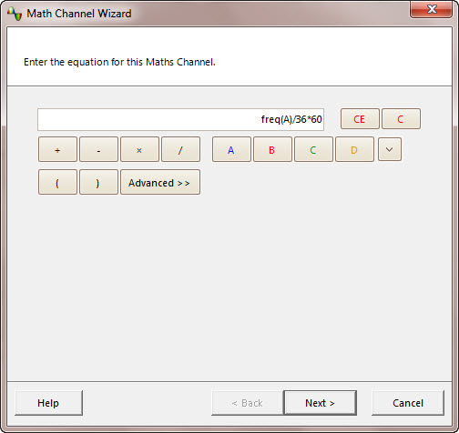
  Here is an example that could be used for an AC producing signal in which the average of the signals amplitude is zero, remember, we don't need to modify the sample point for this one:

    (freq A) / 36 * 60 =  RPM  of a 36 tooth reluctor
SCREENSHOT_OF_36_TOOTH_RELUCTOR.jpg (38 KB | 560 )
Title: Re: Maths channel - crank sensor to frequency
Post by andyz on Feb 14th, 2014 at 6:03am
Hi Preston,

I'd like to apply this specifically to one vehicle at the moment but the understanding of how to create the maths channel would also allow me to apply this method on other vehicles.
I'm currently working on BMW that has a customer complaint of rough idle at first cold start of the day. I've had one opportunity to start the vehicle from cold and I did experience the concern - the engine had a slight roughness to it. No misfire codes are set and apparently the vehicle has already had spark plugs/ignition coil and an injector fitted elsewhere for this fault.
From past experience with this engine I already have my suspicions what will be causing this but I want to see if I can use the scope to prove my suspicions.
I'll leave my hunch out of this thread for now in case anybody wants to take a look at the captures I make along the way (providing I get the time to get the captures that is  :)) and figure out what the problem is.
I wanted to start by using the crank sensor/maths channel vs no 1 sync to see if i can show which cylinder/s are not contributing as much during the warm up.
Would you like me to post crank sensor vs a no 1 sync as a starting point?
What are your thoughts about using this to show the rough running?

Thanks


Title: Re: Maths channel - crank sensor to frequency
Post by PRESTON on Feb 14th, 2014 at 6:13am
Yeah, if you can post the file that would be great.

Title: Re: Maths channel - crank sensor to frequency
Post by andyz on Feb 14th, 2014 at 6:20am
Thanks Preston,
I'll grab it tomorrow and have a go at posting it up.
The subscription will happen - but I first need to figure out a way of hiding it from the wife.
I've been spending way to much on tools recently and i've been told she's watching me closely  ;D


Title: Re: Maths channel - crank sensor to frequency
Post by Tom Roberts on Feb 14th, 2014 at 8:31am

Gee....That one sounds familiar.  Might be totally unrelated though.

BMW misfire cold:

http://www.autonerdz.com/cgi/yabb2/YaBB.pl?num=1340244663/0

This thread is in the Picogroup area though. RPM graphing with PicoScope revealed the problem in this case.

If that is a 60-2 CKP then frequency = RPM.  Makes it simple.   ;)

Yeah, put up your captures...


PRESTON wrote on Feb 14th, 2014 at 5:21am:
Unfortunately it would appear that all the goods ones are in the Picogroup area.


Where they should stay....There is a good reason for that.....   ::)

Title: Re: Maths channel - crank sensor to frequency
Post by PRESTON on Feb 14th, 2014 at 10:44am

Tom Roberts wrote on Feb 14th, 2014 at 8:31am:
Where they should stay....There is a good reason for that.....


  Yes Tom you are right, I guess I meant unfortunately for Andyz in particular, not generically  :).  Hence...


PRESTON wrote on Feb 14th, 2014 at 5:21am:
Got $650.00?


Title: Re: Maths channel - crank sensor to frequency
Post by Logic on Feb 14th, 2014 at 10:48am

andyz wrote on Feb 14th, 2014 at 6:03am:
Hi Preston,

I'd like to apply this specifically to one vehicle at the moment but the understanding of how to create the maths channel would also allow me to apply this method on other vehicles.
I'm currently working on BMW that has a customer complaint of rough idle at first cold start of the day. I've had one opportunity to start the vehicle from cold and I did experience the concern - the engine had a slight roughness to it. No misfire codes are set and apparently the vehicle has already had spark plugs/ignition coil and an injector fitted elsewhere for this fault.
From past experience with this engine I already have my suspicions what will be causing this but I want to see if I can use the scope to prove my suspicions.
I'll leave my hunch out of this thread for now in case anybody wants to take a look at the captures I make along the way (providing I get the time to get the captures that is  :)) and figure out what the problem is.
I wanted to start by using the crank sensor/maths channel vs no 1 sync to see if i can show which cylinder/s are not contributing as much during the warm up.
Would you like me to post crank sensor vs a no 1 sync as a starting point?
What are your thoughts about using this to show the rough running?

Thanks


You will not be able to find the particular fault in that car with your Picoscope.

I would only inform a member of the members group what the issue is...sorry


Title: Re: Maths channel - crank sensor to frequency
Post by andyz on Feb 14th, 2014 at 4:32pm
Hi guys,

Tom, I totally understand why it has to be this way.

This capture was taken at first cold start. The engine was slightly uneven until 2m 12s ish.

Appreciate any input/criticism of the capture.

many thanks
https://www.autonerdz.com/cgi/yabb2/YaBB.pl?action=downloadfile;file=PL87724_E46_M54_cnk_vs_primary_current_vs_maf_at_cold_start_while_engine_runs_slightly_rough_2_no_dtc_001.psdata (2187 KB | 454 )

Title: Re: Maths channel - crank sensor to frequency
Post by Logic on Feb 14th, 2014 at 5:15pm

andyz wrote on Feb 14th, 2014 at 4:32pm:
Hi guys,

Tom, I totally understand why it has to be this way.

This capture was taken at first cold start. The engine was slightly uneven until 2m 12s ish.

Appreciate any input/criticism of the capture.

many thanks


You will need to do some work on sample rates, your capture is not going to demonstrate the parameters that you seek.

Once again there are very good examples in the members area.

Also you did not post any details on the vehicle, no chassis number , no quick test report etc..

Diagnosis is a matter using a range of available tools effectively, if you want consultation, become a member and post all the appropriate detail.

You will be blown away at what there is to learn., if you want to step outside the control and apply science to the issue the members area is where you need to be.

Title: Re: Maths channel - crank sensor to frequency
Post by Logic on Feb 14th, 2014 at 5:16pm
notwithstanding my previous comment and view that the picoscope is not going to resolve this issue for you.

Title: Re: Maths channel - crank sensor to frequency
Post by Tom Roberts on Feb 15th, 2014 at 8:34am

andyz wrote on Feb 14th, 2014 at 4:32pm:
Tom, I totally understand why it has to be this way.


Thank you for your understanding.

As Logic mentioned, your sample rate is poor in your capture with 200µs sample intervals.  That's why everything looks distorted.  I applied a freq math channel to the CKP but it didn't work out very well with the CKP all distorted.

But, I didn't see anything there that seemed symptom related unless it may be in the detail that's not there.

Totally different system than the case I linked to so that doesn't apply.

Later...

Just a suggestion on your file naming....Keep them short and sweet.  No need for details....that's what the PicoScope notes area is for.   ;)

Title: Re: Maths channel - crank sensor to frequency
Post by Gail Taylor on Feb 15th, 2014 at 9:00am
To address the vehicle concern I would need to know what vehicle you are working on. Just BMW leaves a wide path... ;D

Identifix mentions intake valve carbon concerns which will give you exactly this type of misfire. The carbon "sucks up" the fuel on initial start and once saturated the cylinder starts firing normally. It may be as simiple as a top engine cleaning or could be realted to the valve train controls.

Again...need more detail on what exactly you are working on.  ;)

Title: Re: Maths channel - crank sensor to frequency
Post by andyz on Feb 16th, 2014 at 9:20pm
Hi Gail
Vehicle is E46 with M54 engine
Runs slightly rough for first two minutes from dead cold
My hunch is hydraulic lifters bleeding overnight
I Wanted to use the scope to see it.
I'm going to recapture cnk vs maf vs cyl 1 primary current with higher sample rate as suggested.
Maybe then a maths channel can be used to graph the rpm
I'm hoping this would at least give me a direction by showing which cylinder/s are contributing less

Tom/logic
Just to confirm the issue with my previous capture was sample rate too low?


Title: Re: Maths channel - crank sensor to frequency
Post by Tom Roberts on Feb 17th, 2014 at 8:46am

andyz wrote on Feb 16th, 2014 at 9:20pm:
Just to confirm the issue with my previous capture was sample rate too low?


Yes.  When you use long capture times you have to step on the gas and put the pedal to the metal.

Title: Re: Maths channel - crank sensor to frequency
Post by AhtiH on Mar 3rd, 2014 at 11:39am
Anyone care to explain how to apply math to signal that has 2.5V zero level?

Title: Re: Maths channel - crank sensor to frequency
Post by Tom Roberts on Mar 6th, 2014 at 8:22am

AhtiH wrote on Mar 3rd, 2014 at 11:39am:
Anyone care to explain how to apply math to signal that has 2.5V zero level?


That has been covered in the Picogroup section. 

Title: Re: Maths channel - crank sensor to frequency
Post by Tom Roberts on Oct 4th, 2014 at 4:33pm

andyz wrote on Feb 14th, 2014 at 4:32pm:
Tom, I totally understand why it has to be this way.


And...  As if to illustrate the point...

Michael Haimes copied and pasted Preston's post in reply #2 to iATN here:

http://members.iatn.net/forums/read/msg.aspx?f=forum8&m=159876&fv=0&ar=0

This is one good reason why the goods are in the Picogroup areas of the forums and need to stay there.   ::)

Title: Re: Maths channel - crank sensor to frequency
Post by JNelson on Oct 4th, 2014 at 5:07pm
Wow! Not just copy and pasted, but a screen shot.   :o

And Tom, you are quick. That was less than an hour between his post and yours?  8-)

Title: Re: Maths channel - crank sensor to frequency
Post by Spence on Oct 5th, 2014 at 5:32am
Seems it has been removed on the iATN forum.  :)

Title: Re: Maths channel - crank sensor to frequency
Post by Spence on Oct 5th, 2014 at 5:44am
Tom, any thoughts of moving this thread into the PicoGroup area?

Title: Re: Maths channel - crank sensor to frequency
Post by Tom Roberts on Oct 5th, 2014 at 8:50am

Spence wrote on Oct 5th, 2014 at 5:32am:
Seems it has been removed on the iATN forum. 


Yes.  They did the right thing.  I let them know and requested it be removed.  As you know, we do the same for them here when someone does that with iATN content.  Maybe some just don't know they can just post a link?

We encourage that.   ;)

This particular board can be read by anyone.  You don't even have to be registered.


Spence wrote on Oct 5th, 2014 at 5:44am:
Tom, any thoughts of moving this thread into the PicoGroup area?


If all the participants in this thread were Picogroup members then I might consider it but they are not and so I don't think that would be appropriate.

Besides, I don't mind a few teasers from time to time to generate some curiosity about what we do here and what might be behind the curtain...   8-)


Title: Re: Maths channel - crank sensor to frequency
Post by Derreck on Oct 6th, 2014 at 2:22pm

Tom Roberts wrote on Oct 5th, 2014 at 8:50am:
I don't mind a few teasers from time to time to generate some curiosity about what we do here and what might be behind the curtain...   Cool


SPOILERS!

Behind the curtain is just Tom pulling various ropes and talking into a microphone ...  ;D

The Autonerdz Community Forums » Powered by YaBB 2.5 AE!
YaBB Forum Software © 2000-2010. All Rights Reserved.