The Autonerdz Community Forums
https://www.autonerdz.com/cgi/yabb2/YaBB.pl
General Public Area >> PicoScope >> Waveform questions
https://www.autonerdz.com/cgi/yabb2/YaBB.pl?num=1304534771

Message started by epetty01 on May 4th, 2011 at 11:46am

Title: Waveform questions
Post by epetty01 on May 4th, 2011 at 11:46am
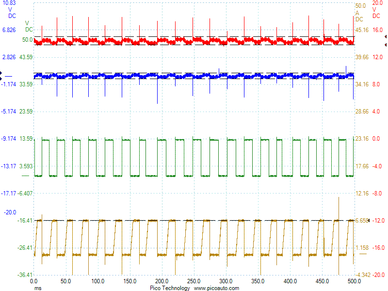
I have a 94 Ford E150 with a 5.8L engine that has an intermittent misfire and would like to share the following scope patterns to see what you think. Actually Tom strongly suggested it, thanks Tom! What you'll see is the PIP(red), SPOUT(green), IDM(blue) and ignition coil secondary(gold). The problem is obvious I just don't know what the cause is, the PIP seems to reverse but the SPOUT signal looks like trash on top not sure if this is an input or output issue. There also seems to be excessive AC voltage on the power supply lines which I can't trace down.

Title: Re: Waveform questions
Post by daveyK on May 4th, 2011 at 11:52am
Hello Eric,

Can you post the psd files?

Thanks,

dave

Title: Re: Waveform questions
Post by epetty01 on May 4th, 2011 at 1:39pm
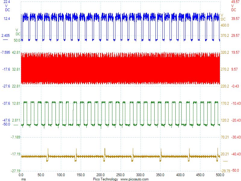
Here you go thought they posted the first time but got more now anyway. The first is at idle, second at 1500 rpm, the third is ign. module power and ground, PIP and ignition current at coil. The fourth is ign. module power and ground, PIP and coil current with SPOUT connector out. The misfire does not happen with SPOUT connector out which indicates the problem is in the PCM but it still surges and acts like the miss is there just not seeing it on the scope.
https://www.autonerdz.com/cgi/yabb2/YaBB.pl?action=downloadfile;file=94_5_8_coil_IDM_PIP_SPOUT_Bad5.psdata (71 KB | )
https://www.autonerdz.com/cgi/yabb2/YaBB.pl?action=downloadfile;file=94_5_8_coil_IDM_PIP_SPOUT_Bad_offidle.psdata (76 KB | )
https://www.autonerdz.com/cgi/yabb2/YaBB.pl?action=downloadfile;file=94_5_8_Ign_+_Ign-_PIP_Coil_Current_Bad5.psdata (254 KB | )
94_5_8_Ign_+_Ign-_PIP_Coil_Current_SPOUTconnectorout.gif (29 KB | )

Title: Re: Waveform questions
Post by Tom Roberts on May 4th, 2011 at 2:51pm
Hi Eric,

You did it.   ;)

Your third data file cannot be downloaded because it has a plus symbol in it.  The server does not like file names with symbols.  Just rename the file and post it again.  The other two work great.

You don't show much detail in your secondary and are missing the KV spikes because your sample rate is turned down so that your sample intervals are 62us apart.

What I see there is a normal PIP and an ICM that is following the SPOUT commands perfectly for a CCD TFI 4 system.  

The SPOUT is  not fine.  I don't know what all that hash is during SPOUT high but SPOUT is disrupted for no apparent reason.  Check PCM powers and grounds, etc.  I think you know where to go from here   ;)

The ignition timing when not acting up is about 19deg BTDC, assuming base timing is set at 10deg and more like 23.5 in the higher RPM capture..  So we do have computed advance online.  Until everything goes wonky....

Title: Re: Waveform questions
Post by Tom Roberts on May 4th, 2011 at 3:51pm

Eric,

I fixed your file name that had the + and - symbols in it and here it is.

PIP looks disrupted there but it's not.  It is just reacting to the SPOUT being low, which is normal.  The low amplitude there is timing notch amplitude.  Same with your other capture where PIP looks funky.  SPOUT is doing that.
https://www.autonerdz.com/cgi/yabb2/YaBB.pl?action=downloadfile;file=94_5_8_Ign_Ign_PIP_Coil_Current_Bad5.psdata (254 KB | )

Title: Re: Waveform questions
Post by epetty01 on May 9th, 2011 at 12:46pm
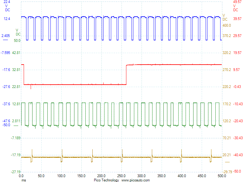
Ok, the vehicle is fixed. The solution was a PCM, I kinda suspected the PCM but when ALL the symptoms did not clear up with the SPOUT disconnected I needed to look further. The consensus was a problem with the EPC driver in the PCM, confirmed by removing that wire from the harness at transmission. I installed a switch inline to open and close the circuit while watching the scope. With the PCM in command of EPC the PIP, SPOUT and basically all circuits that shared the power feed from the PCM relay were trashed. It also had about 365mv AC riding on that circuit. The AC voltage would decrease with an increase in engine RPM, not sure why. With the EPC control switched off everything returned to normal including the AC voltage dropping to <20mv. I checked the EPC solenoid for a short to ground and resistance(5 ohms), both were in spec. I am having a hard time understanding what exactly happened here, how can the EPC driver create AC voltage? Was the AC voltage causing the PCM to wig out? Was the AC voltage being created somehwere in that circuit and the PCM had a bad capacitor? KOEO it had 265mv AC on that circuit, that's w/o the fuel pump running, where is that coming from? I attached two more waveforms with and w/o EPC control, the w/o EPC control is identical to the waveform after the PCM was replaced. Thank you for all for all the help Tom.

94_5_8_SPOUT_EPC_PIP_SPOUT_Inj_8_with_EPC_control.gif (30 KB | )
94_5_8_SPOUT_EPC_PIP_SPOUT_Inj_8_without_EPC_control.gif (25 KB | )

Title: Re: Waveform questions
Post by Tom Roberts on May 9th, 2011 at 1:01pm

Thanks for sharing this with us, Eric.  Glad you got it fixed.    [smiley=woohoo.gif]

Glad we could help.  Didn't want to see you going down the rabbit hole on this one chasing PIP as others had suggsted elsewhere.

Hope you hang out here more often.   ;)

The Autonerdz Community Forums » Powered by YaBB 2.5 AE!
YaBB Forum Software © 2000-2010. All Rights Reserved.