The Autonerdz Community Forums
https://www.autonerdz.com/cgi/yabb2/YaBB.pl
General Public Area >> Autonerdz Training >> Electric Motors in CD1
https://www.autonerdz.com/cgi/yabb2/YaBB.pl?num=1233463018

Message started by Sam1 on Jan 31st, 2009 at 8:36pm

Title: Electric Motors in CD1
Post by Sam1 on Jan 31st, 2009 at 8:36pm
Hi

In Nerds CD1, Part 6, at the start of time 1:00, the instructor speaks about the amps being 28, but the scope is not showing amps rather 2.8v, do I take it what the resistance of the motor is 0.1 and I=VR? but if so, why was not it indicated? am I missing something?

thx

Title: Re: Electric Motors in CD1
Post by TCROfreak on Jan 31st, 2009 at 10:17pm
Sam,
I will try and answer the best I can and I am sure Tom will help with what I miss.
A scope measures voltage changes over time.  The scope by itself cannot read amps therefore an inductive amp clamp must be used.  In the video you see a reading of 2.8v because that amp clamp being used has an output of 100mv per amp.  

Here is a link to an inductive amp clamp on Pico's web site, http://www.picoauto.com/current-clamp-small.html if you purchase a Pico Auto kit I believe it is included I know it is was with mine I purchased from Tom.

Title: Re: Electric Motors in CD1
Post by Sam1 on Feb 1st, 2009 at 1:08am
thanks for that.

why would not the scope run its own functions and just display the amp according to the setting of the clamp?

Title: Re: Electric Motors in CD1
Post by Carl Grotti on Feb 1st, 2009 at 8:45am
Sam,

Tom was using his Fluke scope to capture that. It will only read voltage over time just like any other scope. Unlike PicoScope or the Modis/Solus, there is no provision in the software for it to make that conversion, So, what you have to do is move the decimal point to the right one digit and then you have converted it to current. In this instance, since the probe outputs 100mV per amp, one digit will give you the true value of the current flowing.

One other thing. You can't really use Mr Ohm's Law to figure out the working resistance. You have to facter in the CEMF (Counter Electromotive Force).

Title: Re: Electric Motors in CD1
Post by Sam1 on Feb 1st, 2009 at 9:35am

Carl Grotti wrote on Feb 1st, 2009 at 8:45am:
So, what you have to do is move the decimal point to the right one digit and then you have converted it to current. In this instance, since the probe outputs 100mV per amp, one digit will give you the true value of the current flowing.


The current clamp has two calibration settings, set by a slider switch on the handle of the probe.

  1. 1 mV/10 mA (100 mV = 1 A)
     — use this for testing currents up to 20A.
  2. 1 mV/100 mA (10 mV = 1 A)
     — use this for testing current up to 60A.

screen                   setting 1                       setting 2

2.8v                       28A                              280A

BTW
which clamp is supplied in the Quadkit, The PP218 or the PP264?

Title: Re: Electric Motors in CD1
Post by Sam1 on Feb 1st, 2009 at 9:48am

Carl Grotti wrote on Feb 1st, 2009 at 8:45am:
Sam,

Tom was using his Fluke scope to capture that. ...


Why not pico since he is a pico man?

Title: Re: Electric Motors in CD1
Post by Carl Grotti on Feb 1st, 2009 at 9:50am

Quote:
BTW
which clamp is supplied in the Quadkit, The PP218 or the PP264?


PP264 Current Clamp (60A AC/DC) with BNC and 3 metre screened lead

PP266 Current Clamp (600A AC/DC) with BNC and 3 metre screened lead

Title: Re: Electric Motors in CD1
Post by Tom Roberts on Feb 1st, 2009 at 10:04am
Sam,

Looks like the guys have pretty well covered it   ;)

Our kits have the PP264 in them.  This one has a nickel shielded case with the long shielded BNC lead.


Quote:
Why not pico since he is a pico man?


I have been working with scopes long before Pico existed.  The Nerd series has captures in it from several different scopes.  It is not Pico specific training but targeted at any scope user.

Pico contacted me when they wanted to enter the automotive field.  Once I got a PicoScope to evaluate, I realized that this was going to be a scope power users dream and took it from there to where we are today.   ;)

Title: Re: Electric Motors in CD1
Post by daveyK on Feb 1st, 2009 at 10:15am
Hi Tom,

And you have done a mighty fine job ;)

Second to none in support and dedication ;) ;)

THANKS Tom !

dave

Title: Re: Electric Motors in CD1
Post by Carl Grotti on Feb 1st, 2009 at 12:49pm
Sam,

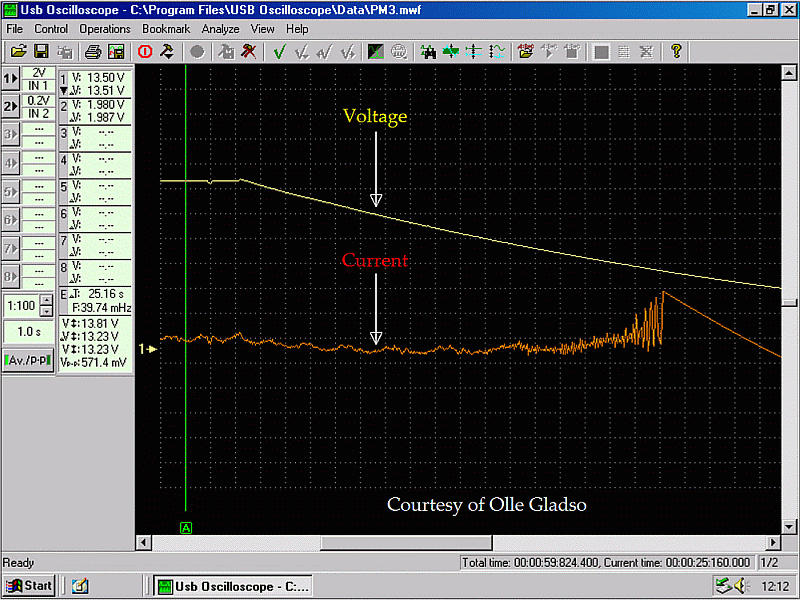
Here is an example of voltage decreasing for an electric motor and yet current remains fairly stable until the end. (Thank you, Olle)

Ohm's Law cannot be applied here.


motorvoltamps.gif (95 KB | )

Title: Re: Electric Motors in CD1
Post by Sam1 on Feb 1st, 2009 at 4:34pm

Carl Grotti wrote on Feb 1st, 2009 at 12:49pm:
Ohm's Law cannot be applied here.


I am not an EE but have always known that V=IR is a non breakable law.
why it can not be applied here?
I am guessing the reason being that there could not possibly be a good explanation for the relation. if so, my question be if R is dropping due to motor getting faster would not that satisfy the change in relation on the graph?
why R changes? maybe R of a slow running motor is affected be EMF and when motor speed increases R starts dropping due to less EMF.... I do not know. just a guess. but if you know why Mr. Ohms fail here, let us know.

BTW, R is not just the static ohm, but rather the resistance, reactance, and impedance.

Title: Re: Electric Motors in CD1
Post by Carl Grotti on Feb 1st, 2009 at 4:59pm
Sam,


Quote:
I am not an EE but have always known that V=IR is a non breakable law.


You would be correct in a fixed circuit, however, we are not discussing that. We are discussing the effects of CEMF.


Quote:
why R changes? maybe R of a slow running motor is affected be EMF and when motor speed increases R starts dropping due to less EMF.... I do not know. just a guess. but if you know why Mr. Ohms fail here, let us know.


You have almost answered your own question. There is a big difference in EMF and CEMF. CEMF is the controlling factor in relation to armature speed.


Title: Re: Electric Motors in CD1
Post by Jim_Wilson on Feb 1st, 2009 at 8:50pm

Quote:
I am not an EE but have always known that V=IR is a non breakable law


Sam, you are correct.

The better answer is that you have an active component involved and so the math becomes more complex. You don't throw the law out.

Any circuit with an active component can be broken down into its different stages and ohms law can be applied to figure out the various values.

CEMF is just another voltage potential in the circuit and the math is exactly the same. You just need to know the given CEMF for that given instant.

The specs needed for motors and such will be hard to come by though. I don't know what Tom covered, but there will be differences between permanent magnet motors and series wound motors (which are mostly a thing of the past in our biz).

A little experimentation and you can come up with some amperage curves. PM motors tend to want to run at a specific rpm range or not run at all.

I would recommend anyone involved with heavy scope useage to take at the minimum a semester class at their local JC. A class that is a "survey of electronics". I opted for a 32 unit program which I have never regretted. It's been a while, I forget things, but it just takes a peek at the old books to bring things back to remembrance.

The only down side is that most all of the classes are biased towards AC circuits. Motors especially. One of the very best I remember is a semester of passive circuit analysis. Simpler by far than that covering active circuits, but all active circuits can be broken down into passive circuits.


Title: Re: Electric Motors in CD1
Post by Jim_Wilson on Feb 1st, 2009 at 9:19pm

Sam1 wrote on Feb 1st, 2009 at 4:34pm:

Carl Grotti wrote on Feb 1st, 2009 at 12:49pm:
Ohm's Law cannot be applied here.


I am not an EE but have always known that V=IR is a non breakable law.
why it can not be applied here?
I am guessing the reason being that there could not possibly be a good explanation for the relation. if so, my question be if R is dropping due to motor getting faster would not that satisfy the change in relation on the graph?
why R changes? maybe R of a slow running motor is affected be EMF and when motor speed increases R starts dropping due to less EMF.... I do not know. just a guess. but if you know why Mr. Ohms fail here, let us know.

BTW, R is not just the static ohm, but rather the resistance, reactance, and impedance.


Take your time constant curve, and the operating rpm of the motor, the number of armature segments, etc... The effective resistance of the motor circuit goes up (until it maxes out) with rpm because your spending more time moving to a new circuit and within the first L/R time constant.

Let's say I had a 12.6v battery that was able to maintain 2000 amps eternally. Now, lets connect it up to a frozen starter (brushes in a completed circuit position). What would our voltage be at the starter?


Title: Re: Electric Motors in CD1
Post by Jim_Wilson on Feb 1st, 2009 at 9:29pm

Quote:
CEMF is just another voltage potential in the circuit and the math is exactly the same. You just need to know the given CEMF for that given instant


I think this might add some clarity, maybe not.  We don't act as if the induced voltage can be sustained at any serious amperage.

So yes, I have a different take on what controls motor speed. Given a properly applied potential (varies on the type of motor), its mostly its torque spec and the applied load. Up to a point, of course.

PM motors once again, tend to want to either run within a given range, or not run at all. That is why starter failures seem so different today than they used to be.

The Autonerdz Community Forums » Powered by YaBB 2.5 AE!
YaBB Forum Software © 2000-2010. All Rights Reserved.